OSC SLIP : MicroOsc
Problématique

Nous voulons une méthode robuste, fiable et universelle pour l'intégration de l'Arduino à l'espace immersif dans un contexte de création multimédia. C'est-à-dire l’intégration de capteurs et actionneurs dans un grand espace où l'ordinateur multimédia, qui doit coordonner les aspects audiovisuels (les projections visuelles, les éclairages, les effets et les diffusions sonores), est distant.

Solution de connectique
La solution proposée essaie de rester peu onéreuse et accessible tout en demeurant fiable (en éliminant les sources d’erreurs potentielles des communications) et très compatible avec les outils de création multimédia.
Dans cette optique, nous choisissons d'utiliser le protocole OSC. La plupart des protocoles (COBS, JSON, FUDI, etc.) permettent une trop grande latitude dans la manière d'organiser les données, et s'appuient donc sur des architectures personnalisées spécifiques à chaque développeur. L'OSC impose une structure particulière de l'information que toutes les applications doivent supporter ce qui rend toute communication plus universelle : tout le monde parle la même langue!
Idéallement, nous utiliserions l'OSC UDP qui voyage par Ethernet. Cependant, parfois un réseau est inacessible ou même certains microcontrôleurs ne possèdent pas de connecteur Ethernet (ou Wi-Fi) et ne permettent pas d'envoyer des messages OSC UDP. Il est donc nécessaire d'utiliser des messages OSC SLIP, qui voyagent par USB série, et de communiquer avec une application qui supporte OSC SLIP ou de relayer les mesages OSC SLIP en OSC SLIP avec des relais OSC SLIP ⇄ UDP.

Connexion sérielle
Code à ajouter à setup()
Il est nécessaire d'initialiser la communication sérielle si elle ne l'a pas été faite avec Serial.begin(115200);.
MicroOsc SLIP
Code à ajouter à l'espace global
Il faut ajouter la bibliothèque MicroOscSlip qui fait partie de MicroOsc et initialiser une instance de MicroOscSlip :
#include <MicroOscSlip.h>
// The number 64 between the < > below  is the maximum number of bytes reserved for incomming messages.
// Outgoing messages are written directly to the output and do not need more reserved bytes.
MicroOscSlip<64> myMicroOsc(&Serial);
Créez une variable pour mesurer le temps pour contrôler la vitesse à laquelle nous envoyons les messages:
unsigned long myChronoStart = 0; // VARIABLE USED TO LIMIT THE SPEED OF THE SENDING OF OSC MESSAGES
Fonction personnalisée à ajouter avant loop()
Il est nécessaire de définir une fonction qui va être appelée lorsqu'un nouveau message OSC va être reçu :
// FUNCTION THAT WILL BE CALLED WHEN AN OSC MESSAGE IS RECEIVED:
void myOscMessageParser( MicroOscMessage& receivedOscMessage) {
   // ADD MESSAGE PARSING CODE HERE
}
À l'intérieur de la fonction que vous venez de créer l'adresse du message peut être validée avec checkOscAddress() ainsi :
if ( receivedOscMessage.checkOscAddress("/address") ) {
	// MESSAGE ADDRESS IS "/address"
}
Lorsque l'adresse du message a été validée, il est possible de récuprer les données. Par exemple, pour récupérer un entier:
int32_t intArgument = receivedOscMessage.nextAsInt();
Voici comment récupérer les autres types de données :
// PARSE AN INT
int32_t intArgument = receivedOscMessage.nextAsInt();
// PARSE A FLOAT
float floatArgument = receivedOscMessage.nextAsFloat();
// PARSE A STRING
const char * s = receivedOscMessage.nextAsString();
// PARSE A BLOB
const uint8_t* blob;
uint32_t length = receivedOscMessage.nextAsBlob(&blob);
// PARSE MIDI
const uint8_t* midi;
receivedOscMessage.nextAsMidi(&midi);
Code à intégrer dans loop()
Déclencher la réception des messages
Dans loop() nous devons déclencher la réception des messages OSC avec la méthode onOscMessageReceived() à laquelle nous passons le nom de la fonctione personnalisée créée précédemment:
myMicroOsc.onOscMessageReceived( myOscMessageParser );
Envoyer des messages
Avant d'envoyer des messages, il faut limiter la vitesse d'envoi selon un intervalle de temps :
// EVERY 50 MILLISECONDS :
if (millis() - myChronoStart >= 50) {
    myChronoStart = millis();           // RESTART CHRONO

    // SEND OSC MESSAGES HERE
}
À l'intérieur de la fonction que vous venez de créer vous pouvez envoyer des messages. Par exemple un entier ainsi :
int myIntToSend = 100;
myMicroOsc.sendInt("/address", myIntToSend);
Voici les autres méthodes pour envoyer les autres types de données :
// SEND AN INT(32)
myMicroOsc.sendInt(const char *address, int32_t i);
// SEND A FLOAT
myMicroOsc.sendFloat(const char *address, float f);
// SEND A STRING
myMicroOsc.sendString(const char *address, const char *str);
// SEND A BLOB
myMicroOsc.sendBlob(const char *address, unsigned char *b, int32_t length);
// SEND DOUBLE
myMicroOsc.sendDouble(const char *address,double d);
// SEND MIDI
myMicroOsc.sendMidi(const char *address,unsigned char *midi);
// SEND INT64
myMicroOsc.sendInt64(const char *address, uint64_t h);
// SEND A MIXED TYPE VARIABLE LENGTH MESSAGE
myMicroOsc.sendMessage(const char *address, const char *format, ...);
Exemple MicroOsc SLIP pour M5Stack Atom Lite
L'exemple suivant montre comment envoyer et recevoir de l'OSC SLIP avec un Atom Lite.
Messages reçus par l'Arduino :
/led int-> éteint (0) ou allume (1) le pixel en blanc/pixel int int int-> change la couleur RGB (0-255 pour chaque couleur)
Messages envoyés par l'Arduino :
/pot int-> envoie la valeur de rotation du M5Stack Agnle Unit/button int-> envoie un 1 si le bouton est appuyé et un 0 sinon
Composants requis
Code
// MicroOSC demo for M5Stack Atom Lite
// by Thomas O Fredericks
// 2023-02-20

// WHAT IS DOES
// ======================
// OSC communication example.
//
// OSC messages received by the Arduino :
// - /led int -> turn off (0) or on (1) the pixel
// - /pixel int int int -> set the pixel color
//
// OSC messages sent by the Arduino :
// - /pot int -> sends the value of the angle unit
// - /button int -> sends the value of the button

// HARDWARE REQUIREMENTS
// ==================
// - M5Stack Atom Lite
// - M5Stack Angle Unit connected to Atom Lite

// REQUIRED LIBRARIES
// ==================
// - MicroOsc
// - M5Atom

// REQUIRED CONFIGURATION
// ======================
// - Set the baud of your computer's serial connection to 115200

#include <M5Atom.h>
#include <FastLED.h>

CRGB mesPixels[1];

#include <MicroOscSlip.h>

// THE NUMBER 64 BETWEEN THE < > SYMBOLS  BELOW IS THE MAXIMUM NUMBER OF BYTES RESERVED FOR INCOMMING MESSAGES.
// MAKE SURE THIS NUMBER OF BYTES CAN HOLD THE SIZE OF THE MESSAGE YOUR ARE RECEIVING IN ARDUINO.
// OUTGOING MESSAGES ARE WRITTEN DIRECTLY TO THE OUTPUT AND DO NOT NEED ANY RESERVED BYTES.
MicroOscSlip<64> myMicroOsc(&Serial);  // CREATE AN INSTANCE OF MicroOsc FOR SLIP MESSAGES

unsigned long myChronoStart = 0;  // VARIABLE USED TO LIMIT THE SPEED OF THE loop() FUNCTION.

// ANGLE UNIT
#define MA_BROCHE_CAPTEUR_ROT 32
int maLectureRotation;


/********
  SETUP
*********/
void setup() {
  M5.begin(false, false, false);
  Serial.begin(115200);
  FastLED.addLeds<WS2812, DATA_PIN, GRB>(mesPixels, 1);
}

/****************
  ON OSC MESSAGE
*****************/
void myOnOscMessageReceived(MicroOscMessage& oscMessage) {

  if (oscMessage.checkOscAddress("/led")) {

    int state = oscMessage.nextAsInt();
    if (state == 0) {
      mesPixels[0] = CRGB(0, 0, 0);
    } else {
      mesPixels[0] = CRGB(255, 255, 255);
    }
    FastLED.show();

  } else if (oscMessage.checkOscAddress("/pixel")) {

    int red = oscMessage.nextAsInt();
    int green = oscMessage.nextAsInt();
    int blue = oscMessage.nextAsInt();
    mesPixels[0] = CRGB(red, green, blue);
    FastLED.show();
  }
}

/*******
  LOOP
********/
void loop() {

  myMicroOsc.onOscMessageReceived(myOnOscMessageReceived);  // TRIGGER OSC RECEPTION

  if (millis() - myChronoStart >= 50) {  // IF 50 MS HAVE ELLAPSED
    myChronoStart = millis();            // RESTART CHRONO

    if ( M5.Btn.isPressed() ) {
      myMicroOsc.sendInt("/button", 1);
    } else {
      myMicroOsc.sendInt("/button", 0);
    }

    maLectureRotation = analogRead(MA_BROCHE_CAPTEUR_ROT);
    myMicroOsc.sendInt("/pot", maLectureRotation);


  }
}
Exemple MicroOsc SLIP pour Arduino Nano (ou similaire)
Composants requis
- Arduino Nano (ou similaire)
- Potentiomètre
- Photorésistance et résitance adéquate
- Bouton d'arcade illuminé
Schéma du circuit
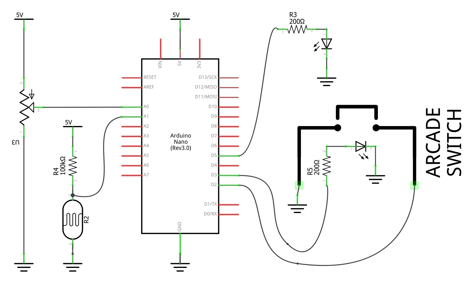
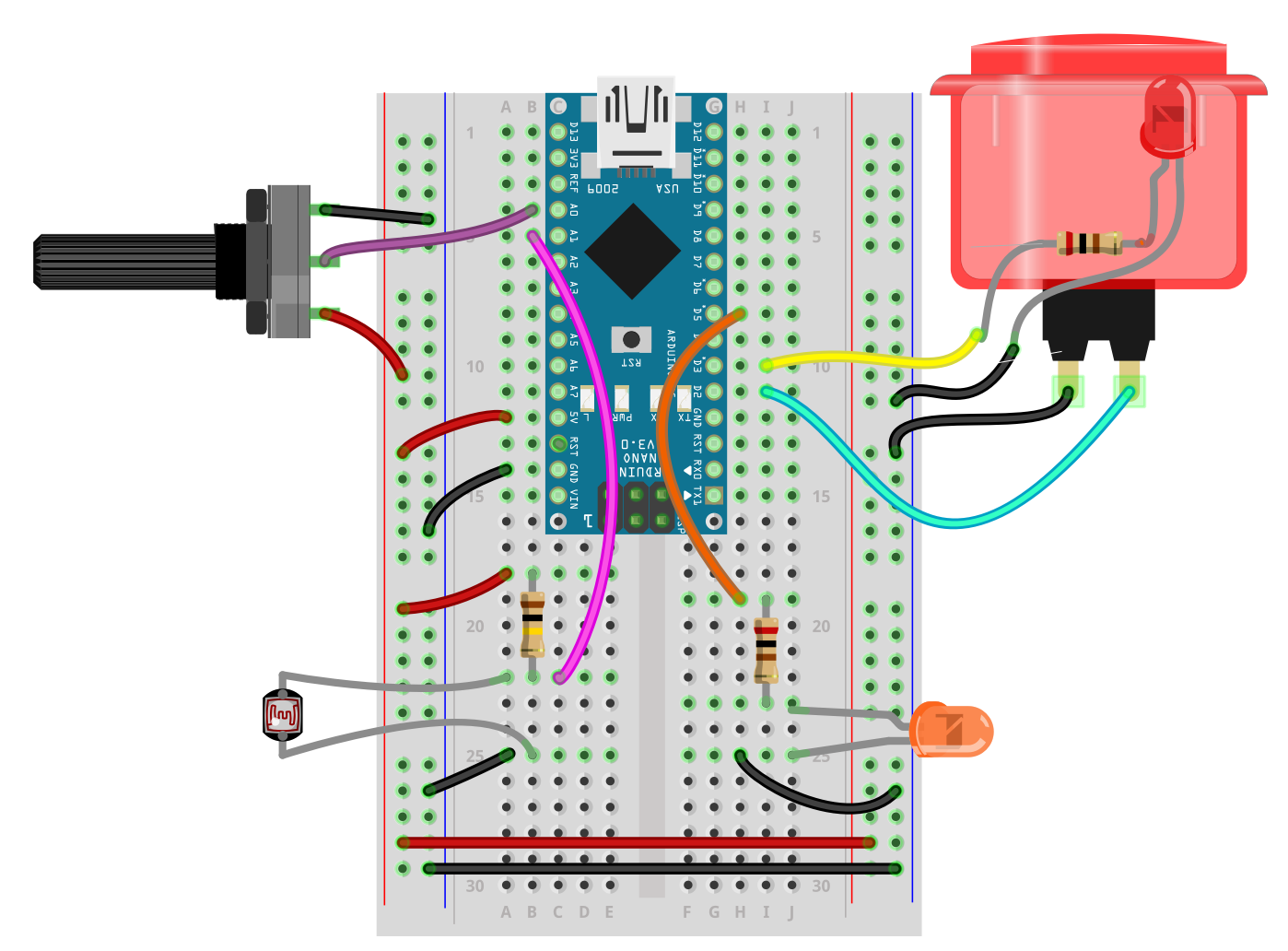
Illustration du circuit
Code OSC SLIP avec MicroOsc pour la démonstration
// MicroOsc_Demo_SLIP
// by Thomas O Fredericks
// 2023-02-20

// WHAT IS DOES
// ======================
// OSC communication example.
//
// OSC messages received by the Arduino :
// - /led int -> turn off (0) or on (1) a LED
// - /pwm int -> set the pwm (0-255) of the arcade button LED
//
// OSC messages sent by the Arduino :
// - /pot int -> sends the value of a potentiometer
// - /photo int -> sends the value of a photocell
// - /button int -> sends the value of a button

// HARDWARE REQUIREMENTS
// ==================
// - POTENTIOMETER connected to analog pin A0
// - POTOCELL (with voltage resistor) connected to analog pin A1
// - Illuminated arcade BUTTON with it's switch connected to pin 2
//   and it's LED connected to pin 3 (will be PWM modulated)
// - LED (and matching resistor) connected to pin 5 (will be turned off or on)

// REQUIRED LIBRARIES
// ==================
// - MicroOsc

// REQUIRED CONFIGURATION
// ======================
// - Set the baud of your computer's serial connection to 115200


#include <MicroOscSlip.h>

// THE NUMBER 64 BETWEEN THE < > SYMBOLS  BELOW IS THE MAXIMUM NUMBER OF BYTES RESERVED FOR INCOMMING MESSAGES.
// MAKE SURE THIS NUMBER OF BYTES CAN HOLD THE SIZE OF THE MESSAGE YOUR ARE RECEIVING IN ARDUINO.
// OUTGOING MESSAGES ARE WRITTEN DIRECTLY TO THE OUTPUT AND DO NOT NEED ANY RESERVED BYTES.
MicroOscSlip<64> myMicroOsc(&Serial);  // CREATE AN INSTANCE OF MicroOsc FOR SLIP MESSAGES

unsigned long myChronoStart = 0;  // VARIABLE USED TO LIMIT THE SPEED OF THE loop() FUNCTION.

// POTENTIOMETER
int myPotPin = A0;
int myPotStoredValue = 0;

// PHOTOCELL
int myPhotoPin = A1;
int myPhotoStoredValue = 0;

// BUTTON
int myButtonPin = 2;
int myButtonSotredValue = 0;

// BUTON LED
int myButtonLedPin = 3;  // PIN MUST SUPPORT PWM

// LED
int myLedPin = 5;

/********
  SETUP
*********/
void setup() {
  Serial.begin(115200);                // START SERIAL COMMUNICATION
  pinMode(myPotPin, INPUT);            // POTENTIOMETER: ANALOG INPUT
  pinMode(myPhotoPin, INPUT);          // PHOTOCELL: ANALOG INPUT
  pinMode(myButtonPin, INPUT_PULLUP);  // BUTTON: DIGITAL INPUT
  pinMode(myButtonLedPin, OUTPUT);     // LED: DIGITAL OUTPUT
  pinMode(myLedPin, OUTPUT);           // LED: DIGITAL OUTPUT
}

/****************
  ON OSC MESSAGE
*****************/
void myOnOscMessageReceived(MicroOscMessage& oscMessage) {

  if (oscMessage.checkOscAddress("/led")) {  // IF THE ADDRESS IS /led
    int newValue = oscMessage.nextAsInt();  // GET NEW VALUE AS INT
    digitalWrite(myLedPin, newValue);       // SET LED OUTPUT TO VALUE (DIGITAL: OFF/ON)

  } else if (oscMessage.checkOscAddress("/buttonLed")) {  // IF THE ADDRESS IS /buttonLed
    int newValue = oscMessage.nextAsInt();  // GET NEW VALUE AS INT
    analogWrite(myButtonLedPin, newValue);       // SET LED OUTPUT TO VALUE (ANALOG/PWM: 0-255)

  }

}

/****************
  POTENTIOMETER UPDATE
****************/
void myPotUpdateValueAndSendIfChanged() {
  int newValue = analogRead(myPotPin);             // READ NEW VALUE
  if (newValue != myPotStoredValue) {              // IF NEW VALUE DIFFERENT THAN STORED VALUE
    myPotStoredValue = newValue;                   // STORE NEW VALUE
    myMicroOsc.sendInt("/pot", myPotStoredValue);  // SEND UPDATED VALUE
  }
}

/*********************
  PHOTOCELL UPDATE
**********************/
void myPhotoUpdateValueAndSendIfChanged() {
  int newValue = analogRead(myPhotoPin);               // READ CURRENT VALUE
  if (newValue != myPhotoStoredValue) {                // IF NEW VALUE DIFFERENT THAN STORED VALUE
    myPhotoStoredValue = newValue;                     // STORE NEW VALUE
    myMicroOsc.sendInt("/photo", myPhotoStoredValue);  // SEND UPDATED VALUE
  }
}

/*********************
  BUTTON UPDATE
**********************/
void myButtonUpdateValueAndSendIfChanged() {
  int newValue = digitalRead(myButtonPin);               // READ CURRENT VALUE
  if (newValue != myButtonSotredValue) {                 // IF NEW VALUE DIFFERENT THAN STORED VALUE
    myButtonSotredValue = newValue;                      // STORE NEW VALUE
    myMicroOsc.sendInt("/button", myButtonSotredValue);  // SEND UPDATED VALUE
  }
}

/*******
  LOOP
********/
void loop() {

  myMicroOsc.onOscMessageReceived(myOnOscMessageReceived);  // TRIGGER OSC RECEPTION

  if (millis() - myChronoStart >= 50) {  // IF 50 MS HAVE ELLAPSED
    myChronoStart = millis();            // RESTART CHRONO

    myPotUpdateValueAndSendIfChanged();  // POTENTIOMETER UPDATE

    myPhotoUpdateValueAndSendIfChanged();  // PHOTOCELL UPDATE

    myButtonUpdateValueAndSendIfChanged();  // BUTTON UPDATE
  }
}